Sidebar
This is an old revision of the document!
Table of Contents
POD

Description
The On-Board Computer collects data from the sensors in the vehicle and logs and transmits them to a Server.
Characteristics
| Weight Pod | 250g (0.55lbs) |
|---|---|
| Weight holding plate | 68g (0.15lbs) |
| Weight Backbone | 420g (0.92lbs) |
| Total weight | 740g (1.62lbs) |
| Backbone power supply voltage | 12-17 VDC |
| Power supply maximum current | 1A |
| Power consumption (average) | 4-7W |
Power consumption not including peripherals
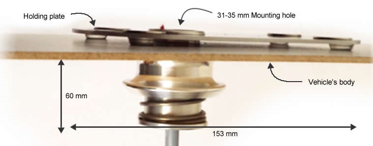
Drawings and Dimensions


3D moldel
Installation before event
Before shipping your vehicle to an event you will need to prepare it to receive the On-Board Computer.
- A 31-35 mm hole in the vehicle body must be drilled before shipping your vehicle. There should be clearance of an equal size to the holding plate (153 x 100 mm and 60 mm depth) inside the vehicle’s body to allow for installation.
 Required clearance inside vehicle’s body
- The hole must be positioned on an area of the body that has a flat, unobstructed surrounding area of 153 x 100 mm (long edge parallel to direction of travel). See the footprint of the On-Board Computer in Figure 2 below.
- The hole should be drilled such that, once mounted, the On-Board Computer Holding Plate will be in a horizontal position, +/- 20°.
- To avoid transmission issues or obstruction of antennae, the selected area must not be covered by any parts of the body or appendages.
Installation at event
Gently pull the plug up through the shaft, connect it to the socket on the underside of the Pod and fasten the nut of the connector. Put the Pod onto the Holding Plate. The magnets will firmly fix device. If the Pod remains loose, check the installation of the Holding plate. The magnets must be on top of the Holding Plate.
Basic Operation
Startup
Push the Start Button on top of the Pod to start the On Board Computer. The device is able to startup when the following conditions are met:
- The Pod is connected to the Backbone
The system will show that it is powered on by the green LED on the Pod and the 12V and 3.3V LEDs on the Backbone.
The power for the sensors will be switched on during startup depending on the configuration.
Troubleshooting
30-60 seconds after the POWER LED is lit, the device checks its own state and the state of the connected sensors. The Backbone holds a configuration of the mandatory sensors. If there is a problem with the on board computer or one of the sensors one or more of the Pod LEDs will flash.
| LEDs | Interpretation | Action |
|---|---|---|
| Starting | Wait up to 60s | |
| Connecting | Wait | |
| Ready | Everything is working fine. Only go on track when you see this pattern |
|
| Problem with Sensor | Ensure all sensors are connected and turned on | |
| Looking for cloud reception | contact technical team if this stays unchaged for more than 5 minutes |
|
| Battery low | Recharge OBC Battery |