Sidebar
This is an old revision of the document!
Relay
The relay contacts (SPDT) are intended to be used to disable the vehicle propulsion system when activitated. Connect these contacts to your motor controller or engine controller. Directly switching the ignition coil primary winding is not permitted because it generates strong EMI emissions which may lead to On-Board Computer malfunction. Wiring your relay in series with the E-Stop is not permitted as well.
There are several options for connecting the shutdown relay. Teams should choose ONLY one option to implement. Other methods will be accepted as long as the drive system is disabled when the relay is activated
Before the event, teams should identify and test with a switch the circuit that will be wired through the shutdown relay.
ICE
- The shutdown relay must kill the engine when the relay is activated.
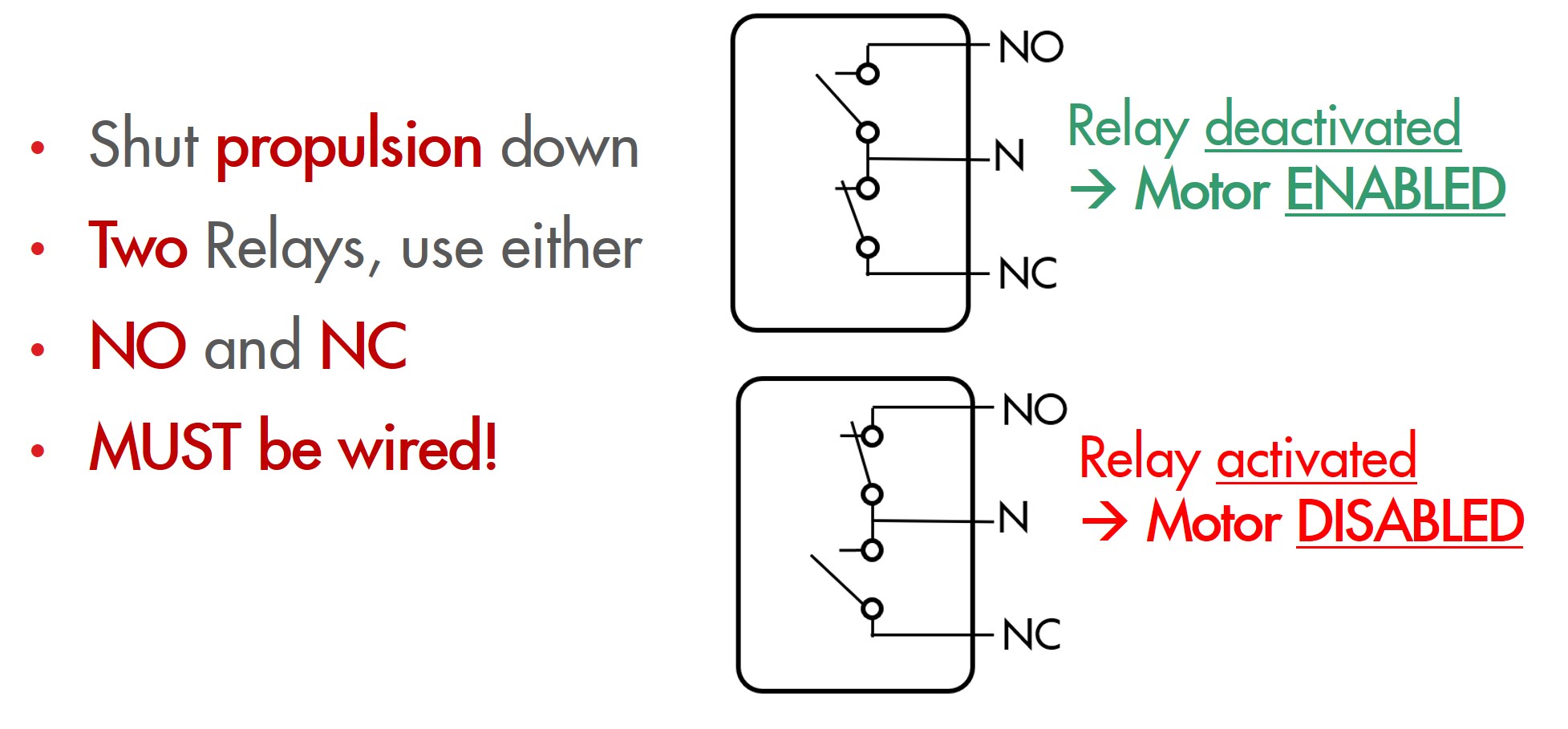
- Connections can made be from N to NC (Normally Closed, will open when relay is activated) or from N to NO (Normally Open, will close when relay is activated) depending on system configuration
- Maximum current = 1 amps
* Option 1 – directly enables engine ECU (NC)
* Option 2 – directly disables engine ECU (NO)
* Option 3 – Connected in series (NC contacts) with deadman switch if electronic
Examples for ICE

THE SHUTDOWN RELAY MUST NOT BE CONNECTED TO THE IGNITION COIL OR E-STOP.
BE & H2
The shutdown relay must disable vehicle propulsion when the relay is activated. Connections can be made from N to NC (Normally Closed, will open when relay is activated) or from N to NO (Normally Open, will close when relay is activated) depending on system configuration. Maximum relay current = 1 amps.
* Option 1 disables motor control when activated
   NC contacts on motor controller on/off
* Option 2 grounds motor controller when activated
   NO contacts for motor controllers with this feature
* Option 3 disables throttle/speed input when activated
    NC contacts to remove motor controller throttle input. Note, you may need to install and pull up/pull down resistor for correct motor controller operation when relay is activated.
Examples for BE and H2

THE SHUTDOWN RELAY MUST NOT BE CONNECTED TO THE E-STOP.