Sidebar
Table of Contents
Joulemeter (JM)

Description
The joulemeters used in Shell Eco-marathon are custom built for Shell and are not available for purchase. The joulemeter (JM) measures voltage across the + and – bus bars and current through the bus bars. The JM calculates joules from measure of voltage, current, and time. The JM will be used in all Shell Eco-marathon energy classes to measure electrical energy flow. Firmware in the JM measures the following;:
- Positive and negative joules,
- Totalized joules,
- Total number of starter motor activations (ICE vehicles),
- Total starter run time (ICE vehicles), and
- Totalized starter joules (ICE vehicles).
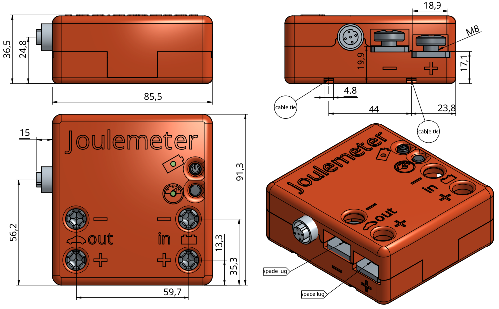
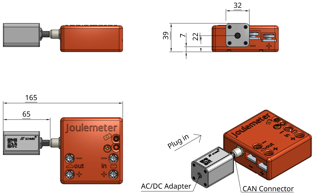
3D model
Installation before event
Joulemeter location in vehicle and other considerations
- Prior to arrival at the event, teams should identify a location to accommodate the Joulemeter near to the battery.
- The Joulemeter may be secured with cable ties, Velcro or other suitable method.
- The LEDs of the Joulemeter must be visible when looking into the engine compartment.
- The Joulemeter “On” switch located on the top of the Joulemeter must be accessible.
Installation at event
- Disconnect the battery from the vehicle electrical system.
- Using the provided spade lugs or equivalent, connect the positive and negative leads in and out of the Joulemeter.
- Secure the Joulemeter with Velcro or cable ties ensuring the LEDs are visible and the on/off push button is accessible.
- Reconnect the battery to the vehicle electrical system.
- For Urban Concept ICE vehicles: connect the CAN cable to the Joulemeter and the On-Board Computer (OBC).
ICE
For all ICE vehicles, the Joulemeter should be installed between the vehicle’s accessory battery and the vehicle’s electrical system. As shown in the figure below, both the positive and negative battery leads pass through the Joulemeter.
For Prototype ICE vehicles, no Joulemeter data cable will be used. Installation diagram: Joulemeter installed in ICE
For Urban Concept ICE vehicles, wire the Joulemeter data cable in series to the Liquid Flowmeter using two CAN cables and a T-Splitter mounted on to the LFM. Connect the Joulemeter as the second device following the Liquid Flowmeter. At the Backbone, use the connector marked „SENSOR“. For the JM, use the USB cable for charging only! See charging instruction below.
For ICE vehicles using hybrid technology with a Supercap, a second JM will be used to measure Supercap voltage. Install wires from the Supercap positive and negative leads to the JM positive and negative input connections. Connect the JM to the CAN network with the help of the T-Splitter and an additional CAN cable. There is no required order of JMs in the CAN connections.

Joulemeter electrical installation (ICE)
See also ICE installation diagrams
BE
For all BE vehicles, the joulemeter should be installed between the propulsion battery and the vehicle electrical system. As shown below, both the positive and negative battery leads pass through the Joulemeter.
For BE Prototype vehicles, no data cable will be used. Installation diagram: Joulemeter installed in BE
For BE Urban Concept vehicles, connect the JM data cable to the „SENSOR“ outlet of the Backbone. For the JM, use the USB cable for charging only! See charging instruction below.

See also BE installation diagrams
H2
The Joulemeter should be installed between the accessory battery and the vehicle’s electrical system. As shown below, both the positive and negative battery leads pass through the Joulemeter.
For Prototype Hydrogen vehicles, no Joulemeter data cable will be used. Installation diagram for H2: Joulemeter installed in H2 Installation diagram for H2 with Supercap: Joulemeter installed in H2 with Supercap
For Urban Concept Hydrogen vehicles, connect the JM data cable to the „SENSOR“ outlet of the Backbone. For the JM, use the USB cable for charging only! See charging instruction below.
For vehicles with a Supercap, a second JM will be used to measure Supercap voltage. Install wires from the Supercap positive and negative leads to the JM positive and negative input connections. Connect the JM to the CAN network with the help of the T-Splitter and an additional CAN cable. There is no required order of JMs in the CAN connections.

See also H2 installation diagrams
Handling
| LED Measurement | |
|
|---|---|---|
| ❶ | Device off | |
| «❶» | Error | |
| «❶» | Initializing | |
| ❶ | Measuring | |
| «❶» | Resetting Values | |
| LED Battery | |
|
| ❷ | Device off | |
| «❷» | low Battery, charging | |
| «❷» | Charging | |
| «❷» | Charging Complete / Operates without battery (Blinks twice followed by pause) | |
| ❷ | Low Battery | |
| ❷ | Charge Battery soon | |
| ❷ | Battery well charged | |
| On/Off Switch | |
|
| Turn the Joulemeter on before going on track and switch it off after you returned | ||
| Reset Button | |
|
| will be handled by technical team if needed | ||
Charging the JM3
For Urban Concept Vehicles, The JM will be supplied with a fully charged battery. If the device is only switched on when connected to a running OBC, the battery will last for the whole event.
For Prototype Vehicles,
 charging process is under development at the moment
A fully charged Battery will last for at least 4 hours.
Charging a fully depleted battery will take about 3+ hours.
Characteristics
| Dimensions | 91.25mm x 85.5mm x 36.5mm (excl. plug) |
|---|---|
| Weight | 300g |
| Battery lifetime | Fully charged to Low Battery > 4 hrs |
| Nominal current range | ±300 A |
| Max. pulse current (1 sec) | 1500 A |
| Nominal voltage range | ±450 V |