User Tools

Site Tools


student_documentation:p_h2

Prototype Hydrogen with Supercapacitor

Autonomous Prototype Urban Concept ICE Hybrid BE H2 Supercapacitor

At the Shell Eco-marathon event, the organizers will provide you with the following telemetry equipment:

Equipment


Joulemeter
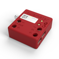
All vehicles are required to install a Joulemeter.

See also 2027 Official Rules Chapter I Article 56: Joulemeters

Joulemeter for supercapacitor

⇒ detailed documentation
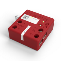
All vehicles that use a supercapacitor are required to install a second Joulemeter.

See also 2027 Official Rules Chapter I Article 63: Vehicles using Hybrid Technology, and Article 65: Hydrogen Fuel Cell vehicles
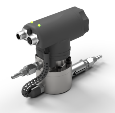
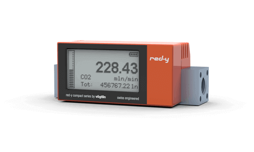
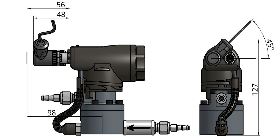
All Hydrogen Fuel Cell teams are required to fit a Vögtlin Red-Y series Hydrogen Flowmeter. This meter shall be fitted according to the Chapter 1 rules and the instructions supplied by the manufacturer.

For all vehicles, the Compact GCM model will be used.

Spec sheets can be found on the Vögtlin website.

Charging equipment
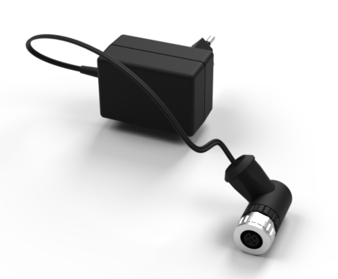
This device is used to charge the sensors.

If charging is done with the charging adapter this device is not needed.
Preparation

Prepare an area in your vehicle for each of the telemetry components.

Refer to the video below and the installation section to find a suitable place for the devices.

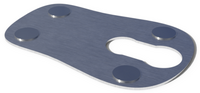
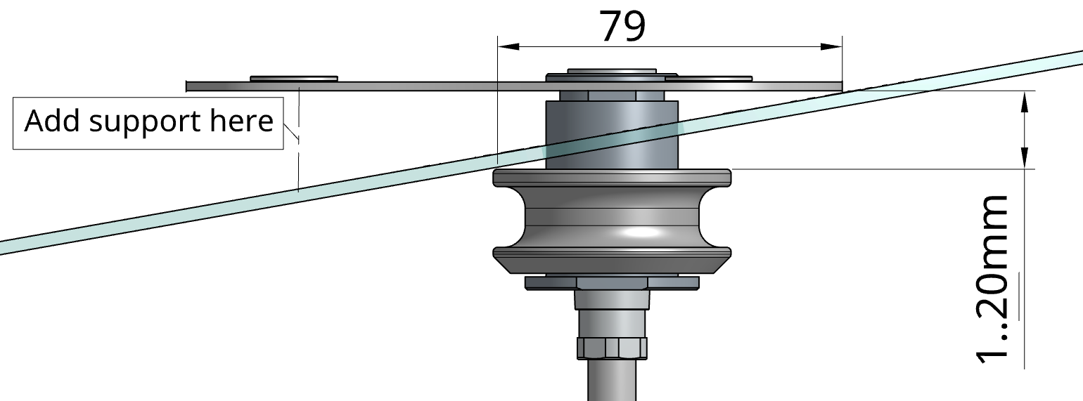
A 31-35 mm hole in the vehicle body must be drilled before shipping your vehicle. There should be clearance of an equal size to the holding plate (153 x 100 x 60 mm) inside the vehicle’s body to allow for installation.
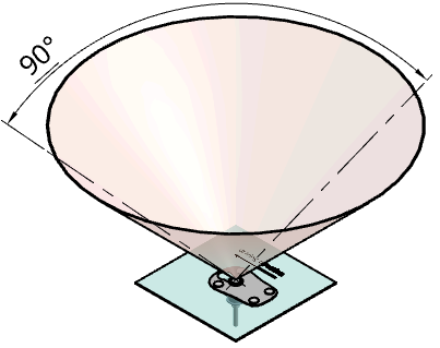
To avoid transmission issues or obstruction of antennae, the selected area must have a clear view to the sky within 90° to all sides.
The hole should be drilled such that, once mounted, the On-Board Computer Holding Plate will be in a horizontal position, +/- 20°.
Support can be added between holding plate and the car body to bring the OBC to a horizontal position. Support the whole lenght and width to prevent the holding plate from bending.

Prototype vehicles can optionally place the OBC inside the car

Fill out the self inspection

Before you can collect the bag containing all the sensors and charging equipment, you must fill out the corresponding self inspection checks.
Watch the following video to learn how to answer the questions correctly:

Note that this video may be an updated version of the one you have already watched.

Installation at the event
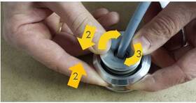
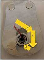
  1. Ensure the spring sits on the shaft.
  2. Pull the torus over the shaft.
  3. Turn the torus to lock it so it cannot slide back.
  4. Push the shaft through the hole in the car roof.
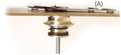
  5. Unlock the torus and let it gently slide back until it looks like (A).
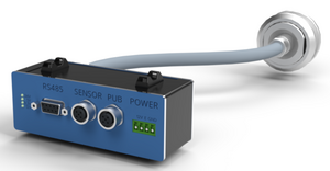
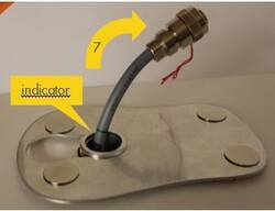
  • Mount the Backbone inside the car such that the cable can be pulled at least 10cm (4“) through the shaft (indicator visible) to the outside of the vehicle. This leaves about 30cm (1ft) of cable and the flexibility to mount the Backbone in a convenient location inside the vehicle.
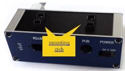
  • There are two zip tie mounting aids on the bottom of the Backbone. They can also be mounted on the top.
  • Insulate the hole in the vehicle body with tape.

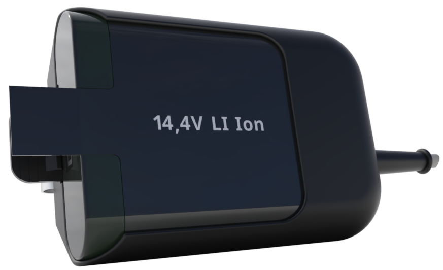
  • Install beltpack so that the battery can be easily removed. (no tape)
  • Install beltpack so that the battery is inserted sideways or up.
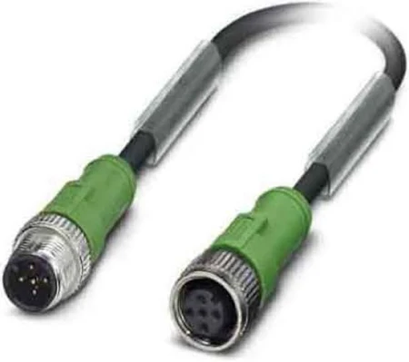
  • Connect the power cable to the Back Bone (BB).
  • Apply a zip tie as strain relief for the power cable near the back bone.

“”“”

Joulemeter

ICE

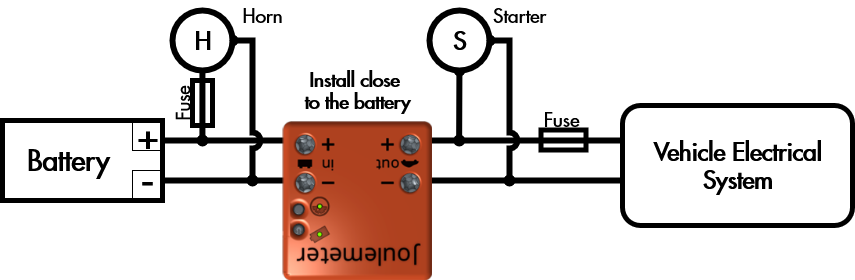
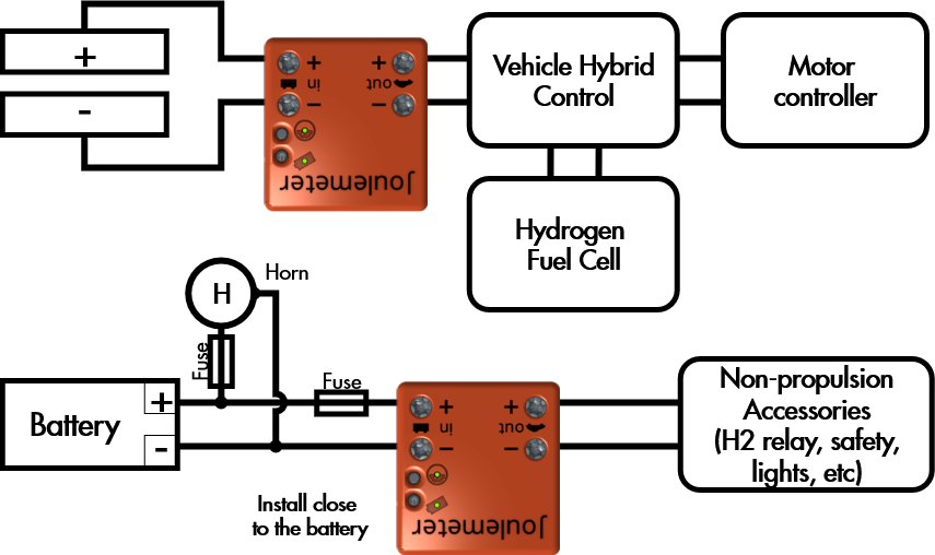
  • The Joulemeter must be installed between the vehicle’s accessory battery and the vehicle’s electrical system.
  • For ICE vehicles using hybrid technology with a Supercap a second JM will be used to measure Supercap voltage. Install wires from the Supercap positive and negative leads to the JM positive and negative input connections.
  • Teams have a choice of powering the horn either before the JM or through the vehicle electrical system.
BE

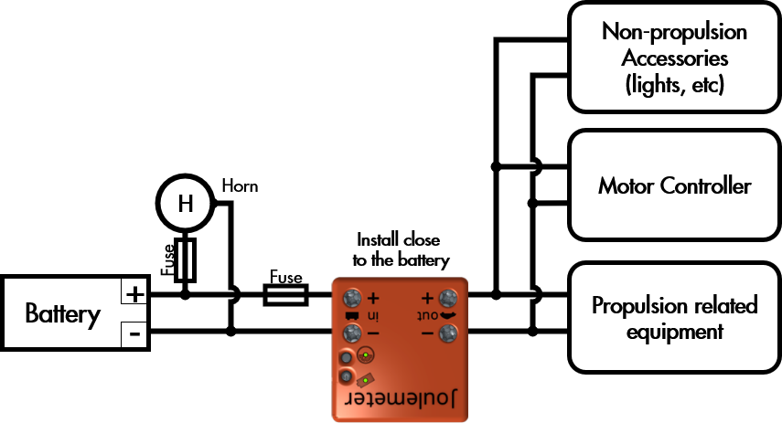
  • The joulemeter must be installed between the propulsion battery and the vehicle electrical system.
  • Teams have a choice of powering the horn either before the JM or through the vehicle electrical system.

H2

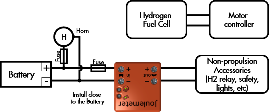
  • The Joulemeter must be installed between the accessory battery and the vehicle’s electrical system.
  • Teams have a choice of powering the horn either before the JM or through the vehicle electrical system.

H2

  • The Joulemeter must be installed between the accessory battery and the vehicle’s electrical system.
  • Teams have a choice of powering the horn either before the JM or through the vehicle electrical system.

H2

  • The Joulemeter must be installed between the accessory battery and the vehicle’s electrical system.
  • Teams have a choice of powering the horn either before the JM or through the vehicle electrical system.

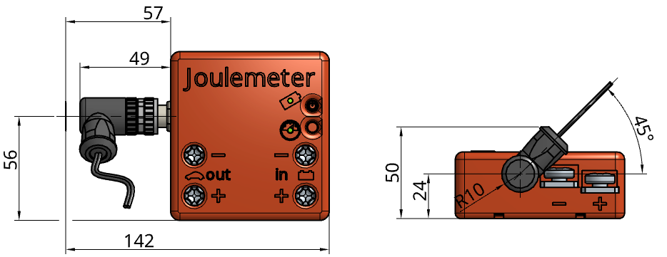
  • The Joulemeter may be secured with cable ties, Velcro or other suitable method.
  • The LEDs of the Joulemeter must be visible when looking into the engine compartment.
  • The Joulemeter “On” switch located on the top of the Joulemeter must be accessible.
  • As shown in the figure, both the positive and negative battery leads pass through the Joulemeter.
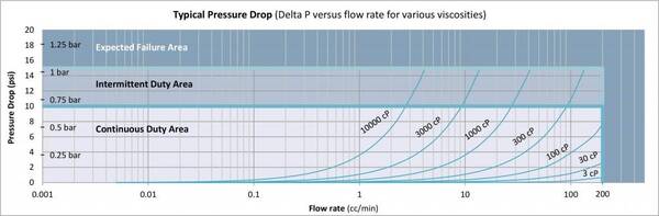
  • LFM location must be below the fuel injector and the fuel tank, preventing air from flowing through the LFM.
  • LFM must be mounted vertically (see drawing in the charging section)
  • The LFM may be secured with cable ties or the two ¼” - 20 NC threaded holes on the bottom.
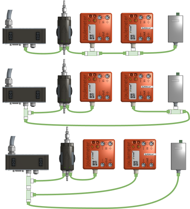
  • The fuel line (6 mm internal diameter) must be safely routed (away from hot exhaust and rotating parts/pinch points) to the pre-determined LFM location with one union and two tube adapters, as shown in Figure below, in place of the LFM.
  • The LEDs of the Liquid Flow Meter must be visible when looking into the engine compartment.
  • The “On” switch located near the electrical connectors must be accessible.
  1. Remove union from fuel line at location of desired flowmeter location
  2. Connect fuel line from fuel tank to the inlet of the fuel filter of the flowmeter
  3. Connect fuel line from the injector to flowmeter outlet
  4. Open the fuel tank valve slowly to allow fuel to fill the lines all the way to the injector (opening fuel line at injector might be required)
  5. Reconnect the fuel line at the injector when most of the air is out of the system
  6. Turn on fuel pressure
  7. Tilt and shake the LFM gently in order to remove remaining air bubbles. (Shell Eco-marathon representatives will finally evacuate the fuel system at tech inspection to ensure all air is out of the fuel system). Manual Activation of the injector, via the ECU or alternate method, to help clear air pockets may help expedite the inspection process.
  8. Mount the LFM to the frame with the 1 ¾” spaced ¼”x 20 bolts on the bottom, or zip tie it to the frame
  9. Check for leaks at all connections!
    (null)
Weight (LFM only) 900g (2lbs)
Dimensions (LFM only) Ø 57mm x 105mm tall (Ø 2.3” x 4.125” tall)
Assembled Dimensions Ø 57mm x 130mm tall x 206mm wide
(Ø 2.3” x 5.1” tall x 8.1” wide)
Flow Range 0.005 to 200 cc/min
Maximum Pressure 500 bar
Ambient Operating Temperature Range -40° to 80°C
Metered Liquid Temperature Range -40° to 90°C
Required Filtration 7 micron
Port Size SAE ¼”
Supply Voltage 5-26 Vdc
Supply Current 25-30 mA typical
Resolution 6000 pulses/cc

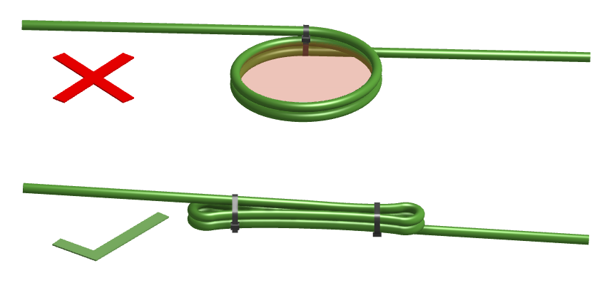
Reduce the area of loops to minimize EMI through induction on the telemetry.
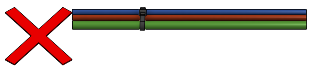
Do not route the telemetry cables in parallel with
- power cables or
-wires with high frequency signals
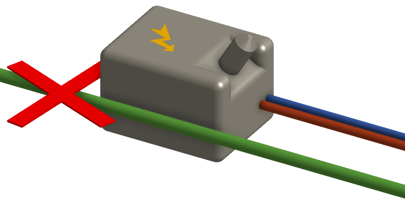
Do not route the telemetry cables close to EMI emitting parts (eg spark plug, starter motor, inverter, valves etc) of the car.
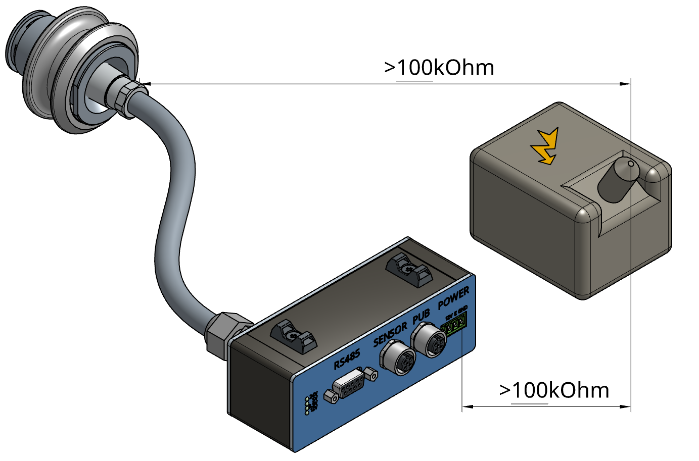
Make sure the whole telemetry system is isolated from your vehicle. The resistance measured between the telemetry system and any part of the vehicle (eg, chassis, negative lead of the battery etc.) must be > 100kΩ.

Handling

On Board Computer (OBC)

  1. The Battery is charged and connected to the Back Bone (BB).
  2. The OBC is connected to the Back Bone (BB)

Back Bone (BB)

Back Bone (BB)

LEDs Interpretation Action
Starting Wait up to 60s
Connecting Wait
Ready Everything is working fine.
Only go on track
when you see this pattern
Problem with Sensor Ensure all sensors are connected and turned on
Looking for cloud reception Contact technical team if this stays
unchanged for more than 5 minutes
Battery low Replace or recharge Battery

Joulemeter

LED Measurement
❶ Device off
«❶» Error
«❶» Initializing
❶ Measuring
«❶» Resetting Values
LED Battery
❷ Device off
«❷» low Battery, charging
«❷» Charging
«❷» Charging Complete / Operates without battery (Blinks twice followed by pause)
❷ Low Battery :!: Not allowed to go on track :!:
❷ Battery ok for 1 attempt :!: Charge Battery soon :!:
❷ Battery good for at least 2 attempts
On/Off Switch
Practice Turn the Joulemeter on before going on track.
Ask the technical team if your consumption can be retrieved.
Turn off after the consumption is read.
Competition Do not touch the Joulemeter until your results are retrieved.
Function Button
Used to initiate fast charging.

LED Measurement
❶ Device off
«❶» Error
«❶» Initializing
❶ Measuring
«❶» Resetting Values
LED Battery
❷ Device off
«❷» low Battery, charging
«❷» Charging
«❷» Charging Complete / Operates without battery (Blinks twice followed by pause)
❷ Low Battery
❷ Charge Battery soon
❷ Battery well charged
On/Off Switch
Practice Turn the LFM on before going on track.
Ask the technical team if your consumption can be retrieved.
Turn off after the consumption is read.
Competition Do not touch the Sensor until your results are retrieved.

Charging

Autonomous Competition

  1. Teams do not need to charge the telemetry system.
  2. Teams are required to turn off the OBC when not used for within next 15 min.
  3. Teams are required to turn off the sensors (JM and LFM) when the OBC is turned off.
  4. The telemetry team replaces low batteries with charged ones if needed.

Mileage Challenge

The teams are responsible for charging the sensors.
A car is not allowed to go on track if the sensor does not show a green or amber battery LED.

step by step

  1. Connect the charging equipment to the power outlet.
  2. Connect the charging equipment to the sensor. :!: Make sure not to bend the pins :!:
  3. Turn on the Sensor (The sensor must be on for the battery to charge.)
  4. (Ignore for LFM) To initiate charging mode on a Joulemeter press the Function button on the Joulemeter for 5sec.
  5. The Sensor's battery LED will be blinking as long as charging is in progress.

Joulemeter

Recharge the Joulemeter whenever it was on for more than 5min.
A fully charged Battery will last for at least 4 hours.
Charging a fully depleted battery will take about 3+ hours.


Returning

right after your last attempt in the autonomous competition

Return the following items at the participant hub right after your last attempt in mileage challenge:

Joulemeter

Joulemeter for supercapacitor

Liquid Flow Meter

Hydrogen Flow Meter

Charging equipment

2025/11/17 09:17 · Beni Ammann
This website uses cookies. By using the website, you agree with storing cookies on your computer. Also you acknowledge that you have read and understand our Privacy Policy. If you do not agree leave the website.More information about cookies
Log In (for D&T Team and Volunteers ONLY) student_documentation/p_h2.txt · Last modified: by Beni Ammann

Page Tools